In order to help you better understand the CenterPoint five-dimensional point cloud pre-processing provided by the DSP sample package, this section analyzes the CPU and DSP reference implementations based on the algorithm principle, and performs consistency verification and performance evaluation on the CPU and DSP reference implementations. The sample package also provides PointPillars four-dimensional point cloud pre-processing, which is similar to CenterPoint. The main feature of the pre-processing of both is to generate pillars pillars through voxelization. This section mainly introduces the implementation of CenterPoint pre-processing, and a separate section introduces the differences in the implementation of PointPillars pre-processing.
This section uses the five-dimensional CenterPoint model as an example. Its corresponding principles and pre-processing algorithm implementation can also be applied to the four-dimensional PointPillars model. The input of the model is five-dimensional point cloud data with a maximum number of 300,000 points. The pre-processing mainly consists of voxelization, feature encoding, quantization and transposition. The pre-processing outputs a feature map of 1x5x20x40064(nchw) and coordinate information of 1x1x40000x4(nhwc).
The coordinates of the cylinder are calculated based on the x and y coordinates of the input five-dimensional point cloud data. The maximum number of cylinders is 40000 and the maximum number of points supported by each cylinder is 20. The calculation principle of the cylinder coordinates is as follows:
Determine whether the x, y, and z of the point cloud are within the valid range and skip invalid point cloud data.
The x and y information of the point cloud can be regarded as a pseudo image, and each pixel in the pseudo image corresponds to a cylinder coordinate.
The coordinates of the input point cloud are unordered, so the cylinder coordinates need to be determined according to the input order of the coordinates. When the number of cylinders exceeds the maximum value limited by the model, no new cylinder will be generated, but the point will be written into the last cylinder.
Points with the same coordinates will be placed in the same cylinder. The model limits the number of points in each cylinder. When the maximum limit is exceeded, the point will be skipped directly.
cur_pillar_id = 0max_pillar_id = 39999max_pt_id_in_pillar = 19for point_cloud in point_clouds:x = point_cloud[0]y = point_cloud[1]z = point_cloud[2]// skip invalid point cloud dataif x or y or z invalid: continue;// calculate the pseudo-image coordinates of the point cloud input x and yidx = (x - back) / x_scaleidy = (y - right) / y_scale// calculate index of pillarif pillars[{idx,idy}] not exist: if cur_pillar_id < max_pillar_id: pt_pillar_id = cur_pillar_id pillars[{idx,idy}] = cur_pillar_id cur_pillar_id += 1 else: pillars[{idx,idy}] = max_pillar_id pt_pillar_id = max_pillar_idelse: pt_pillar_id = pillars[{idx,idy}]// calculate point index in pillarif pillar_nums[pt_pillar_id] < max_pt_id_in_pillar pt_id_in_pillar = pillar_nums[pt_pillar_id] pillar_nums[pt_pillar_id] += 1else pt_id_in_pillar = max_pt_id_in_pillar
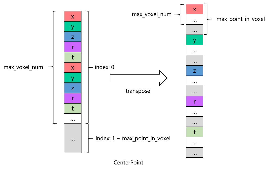
The layout mode of the feature map input to the model is NCHW, and the transposition transforms the shape of the feature map from 1x40000x20x5 to 1x5x20x40064.
The source code of the CPU reference implementation is located in AI Benchmark. The basic pre-processing process is consistent with the principle introduction, in which quantization is incorporated into the feature encoding step.
void QATCenterPointPreProcessMethod::GenVoxel(int start, int end) { for (int i = start; i < end; i++) { float *point; point = point_cloud_data_ + i * config_->kdim; float &point_x = point[0]; float &point_y = point[1]; float &point_z = point[2]; float &point_r = point[3]; // check if x,y,z within the valid range, and skip invalid // point cloud data if (point_x <= config_->kback_border || point_x >= config_->kfront_border || point_y <= config_->kright_border || point_y >= config_->kleft_border || point_z <= config_->kbottom_border || point_z >= config_->ktop_border) { continue; } // calculate pseudo-image coordinates int idx = (point_x - config_->kback_border) / config_->kx_scale; int idy = (point_y - config_->kright_border) / config_->ky_scale; // convert pseudo-image coordinates into index, which as the // key, and check whether the coordinates of pillar have been set int pillar_index = idy * config_->kx_length + idx; int voxelidx = config_->coor_to_voxel_idx[pillar_index]; // config_->coor_to_voxel_idx has been init to -1 // -1 indicates that the coordinate of the pillar has not been set if (voxelidx == -1) { // if the number of pillar is less than the max value, // update the pillar coordiate; otherwise, use the max value if (voxel_num_ < config_->kmax_num_point) { voxelidx = voxel_num_; voxel_num_ += 1; } else { voxelidx = config_->kmax_num_point - 1; } // update pillar index config_->coor_to_voxel_idx[pillar_index] = voxelidx; // write coordinate of pillar config_->coors[voxelidx * 4 + 1] = 0; config_->coors[voxelidx * 4 + 2] = idy; config_->coors[voxelidx * 4 + 3] = idx; } if (config_->pillar_point_num[voxelidx] >= config_->kmax_num_point_pillar) { continue; } else { // calculate offset of point cloud by pillar coordinate and // point index in pillar auto total_offset = (config_->kmax_num_point_pillar * voxelidx + config_->pillar_point_num[voxelidx]) * config_->kdim; // update point numbers in pillar config_->pillar_point_num[voxelidx] += 1; // write point cloud data to pillar *(voxel_data_ + total_offset) = point_x; *(voxel_data_ + total_offset + 1) = point_y; *(voxel_data_ + total_offset + 2) = point_z; *(voxel_data_ + total_offset + 3) = point_r; *(voxel_data_ + total_offset + 4) = point[4]; } }}
// using 'to nearest' float round modestatic inline float round(float const input) { std::fesetround(FE_TONEAREST); float const result{std::nearbyintf(input)}; return result;}void QATCenterPointPreProcessMethod::TransposeDim5(int model_aligned_w) { // Transpose to 1x5x20x40000 int kWC = config_->kmax_num_point_pillar * config_->kdim; int kHW = config_->kmax_num_point * config_->kmax_num_point_pillar; // there c h w is not the model real nchw, just define the order index for (int c = 0; c < config_->kdim; ++c) { int input_wh = c * config_->kmax_num_point_pillar * model_aligned_w; for (int w = 0; w < config_->kmax_num_point_pillar; ++w) { int input_h = input_wh + w * model_aligned_w; for (int h = 0; h < voxel_num_; ++h) { int old_index = h * kWC + w * config_->kdim + c; int new_index = h + input_h; float features_tmp = round(static_cast<float>(voxel_data_[old_index])); // limit the range of feature data to quantized [-128.0f, 127.0f] features_tmp = std::min(std::max(features_tmp, -128.f), 127.f); features_s8_[new_index] = static_cast<int8_t>(features_tmp); } } }}
The acceleration implementation of operations on DSP is mainly considered in two aspects.
Firstly, the calculation part of the operator can be vectorized as much as possible to fully utilize the DSP's computing power, as the DSP on J6 supports 1024-bit SIMD.
Secondly, the memory access part of the operator can be optimized by moving data to the two 256kB TCM on J6's DSP, which have access performance similar to the cache on the CPU, effectively saving memory access overhead. At the same time, the DSP also provides vectorized memory access instructions to improve access efficiency.
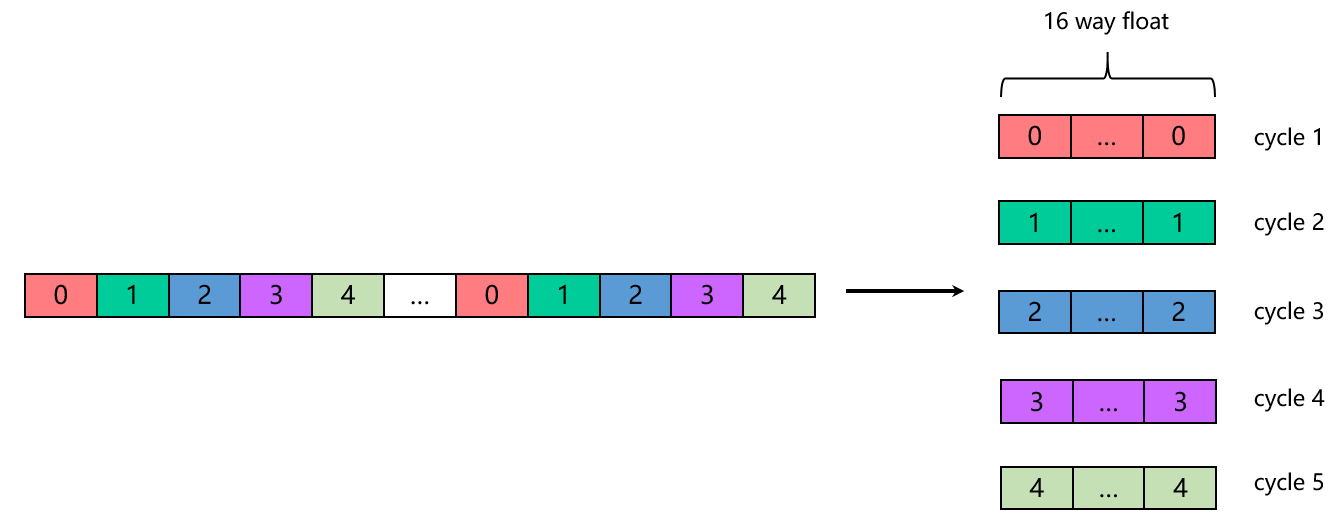
For the five-dimensional model, the calculation process can be divided into 5 cycles, with each cycle calculating one dimension using IVP vector instructions to complete the operation.
Specifically regarding the CenterPoint point cloud pre-processing algorithm, the calculation processes such as calculating the coordinates of pseudo-images, feature encoding, and quantization can all be independently calculated for each dimension. Therefore, it is easy to convert them into vectorized calculations.
The point cloud input data is unordered from the x and y dimensions, which leads to the calculated cylinder coordinates and the index of the cylinder midpoint are also unordered, resulting in random memory access instead of more efficient sequential operations. Since there is no data cache on the DSP, random memory access is very unfriendly, so it is necessary to make full use of the TCM on the DSP. There are only two 256kB TCMs available on the DSP, and the address space of the feature data output is 40000x20=781.25kB, which is much larger than the memory size of the TCM. At the same time, when calculating the voxel coordinates, a pseudo-image coordinate and cylinder coordinate lookup table is also required. The memory required for this table is 512x512x4=1MB (512 is the width and height of the pseudo image, and 4 is the number of bytes required for the cylinder coordinates), which is also far beyond the memory size of the TCM. Considering that it is too costly to move random memory access to the DSP, the calculation and memory access in the pre-processing algorithm are separated, and the calculation part is placed on the DSP, while part of the random access is stored on the CPU for execution. At the same time, in order to reduce the amount of data accessed, the DSP acceleration implementation adjusts the steps of the CPU implementation, bringing feature encoding and quantization forward to after calculating the pseudo-image coordinates. Through this processing, the amount of data required for memory access in the subsequent voxelization and transposition steps will be greatly reduced. Although this will increase the amount of calculation, it can be seen from actual evaluation that reducing the amount of memory access data will bring greater benefits, especially when the number of valid point clouds is large.
Although there are two 256kB TCMs, only one of them is used in each calculation cycle. The main reasons are as follows:
Pingpong buffer is needed to reduce the time waiting for data copying to complete;
Pingpong buffer needs to be located in different TCMs to reduce data bank conflicts.
The calculation on the DSP is divided into two parts, one is to calculate the pseudo image coordinates, and the other is feature encoding, quantization and transposition.
Calculation of pseudo image coordinates, in each calculation cycle, the input is five-dimensional point cloud data, and the output is single-dimensional data. The input-to-output ratio is 5:1, so the input-to-output TCM memory size ratio is also 5:1;
Feature encoding, quantization and transposition, in each calculation cycle, the input is five-dimensional point cloud data, and the output is quantized single-dimensional data. The input-to-output ratio is 20:1.
For the IVP instructions of DSP, please refer to the document ISA/NewISAhtml/index.html provided by Cadence. For a detailed introduction to the TCM memory management interface, please refer to Xtensa Vision Tile Manager Library User's Guide. For a detailed introduction to the IDMA related interfaces, please refer to Xtensa System Software Reference Manual.
#Calculate Pseudo-image Coordinates, Feature Encoding and Transpose(DSP Calculation Part)
The method of calculating pseudo image coordinates is basically the same as that in the CPU reference implementation. The main differences are as follows:
Remove the calculation of one-dimensional coordinates, and store the pseudo image x and y coordinates through the high and low 16 bits of 32 bits (the width and height of the pseudo image of the example model are 512, and 16 bits are enough to store), and use the two-dimensional coordinates as an index to find the corresponding cylinder coordinates.
When filtering invalid point cloud data, use mask move instead of conditional judgment statements. Because using conditional judgment in the inner loop will significantly reduce the computing performance.
#define CALC_POINTPILLAR_ID() \ xb_gsr gs = IVP_GATHERAN_2XF32(p_input, offset[0]); \ xb_vecN_2xf32 const point_x = IVP_GATHERDN_2XF32(gs); \ \ gs = IVP_GATHERAN_2XF32(p_input, offset[1]); \ xb_vecN_2xf32 const point_y = IVP_GATHERDN_2XF32(gs); \ \ gs = IVP_GATHERAN_2XF32(p_input, offset[2]); \ xb_vecN_2xf32 const point_z = IVP_GATHERDN_2XF32(gs); \ \ gs = IVP_GATHERAN_2XF32(p_input, offset[3]); \ xb_vecN_2xf32 const point_r = IVP_GATHERDN_2XF32(gs); \ \ /* calculate pseudo-image coordinates using the IVP instruction */ \ xb_vecN_2xf32 const vf_idx = \ IVP_DIVN_2XF32(IVP_SUBN_2XF32(point_x, (xb_vecN_2xf32)param->back), \ (xb_vecN_2xf32)param->x_scale); \ xb_vecN_2xf32 const vf_idy = \ IVP_DIVN_2XF32(IVP_SUBN_2XF32(point_y, (xb_vecN_2xf32)param->right), \ (xb_vecN_2xf32)param->y_scale); \ \ /* float32_t -> int32_t */ \ xb_vecN_2x32v const vi_idx = IVP_TRUNCN_2XF32(vf_idx, 0); \ xb_vecN_2x32v const vi_idy = IVP_TRUNCN_2XF32(vf_idy, 0); \ \ /* store idy in the high 16 bits and idx in the low 16 bits */ \ xb_vecN_2x32v pillar_index = IVP_SLLN_2X32(vi_idy, 16); \ pillar_index = IVP_ADDN_2X32(pillar_index, vi_idx); \ \ /* check whether the point cloud data is valid */ \ vboolN_2 const px_le = IVP_ULEN_2XF32(point_x, param->back); \ vboolN_2 const px_ge = IVP_ULEN_2XF32(param->front, point_x); \ vboolN_2 const py_le = IVP_ULEN_2XF32(point_y, param->right); \ vboolN_2 const py_ge = IVP_ULEN_2XF32(param->left, point_y); \ vboolN_2 const pz_le = IVP_ULEN_2XF32(point_z, param->bottom); \ vboolN_2 const pz_ge = IVP_ULEN_2XF32(param->top, point_z); \ \ vboolN_2 skip = IVP_ORBN_2(px_le, px_ge); \ skip = IVP_ORBN_2(skip, py_le); \ skip = IVP_ORBN_2(skip, py_ge); \ skip = IVP_ORBN_2(skip, pz_le); \ skip = IVP_ORBN_2(skip, pz_ge); \ /* mask the pseudo-image coordinates of invalid point cloud data as -1 */ \ pillar_index = IVP_MOVN_2X32T(-1, pillar_index, skip); \ /* store pseudo-image coordinates to output */ \ IVP_SCATTERN_2X32(pillar_index, p_output, id_offset)#define CHECK_POINTPILLAR_PARAM() \ LOGE_IF_COND_RETURN(((param.stage != 0U && param.stage != 1U)), \ HB_ERR_INVALID_ARGUMENT, "stage only support 0 or 1"); \ LOGE_IF_COND_RETURN((param.num_points <= 0U), HB_ERR_INVALID_ARGUMENT, \ "num_points must greater than 0"); \ LOGE_IF_COND_RETURN((param.max_num_points <= 0U), HB_ERR_INVALID_ARGUMENT, \ "max_num_points must greater than 0"); \ LOGE_IF_COND_RETURN((param.max_num_points_align <= 0U), \ HB_ERR_INVALID_ARGUMENT, \ "max_num_points_align must greater than 0"); \ LOGE_IF_COND_RETURN((param.max_num_point_pillars <= 0U), \ HB_ERR_INVALID_ARGUMENT, \ "max_num_point_pillars must greater than 0"); \ LOGE_IF_COND_RETURN((param.max_num_point_pillars_align <= 0U), \ HB_ERR_INVALID_ARGUMENT, \ "max_num_point_pillars_align must greater than 0"); \ LOGE_IF_COND_RETURN(!(param.front > param.back), HB_ERR_INVALID_ARGUMENT, \ "front must greater than back"); \ LOGE_IF_COND_RETURN(!(param.left > param.right), HB_ERR_INVALID_ARGUMENT, \ "left must greater than right"); \ LOGE_IF_COND_RETURN(!(param.top > param.bottom), HB_ERR_INVALID_ARGUMENT, \ "top must greater than bottom"); \ LOGE_IF_COND_RETURN(!(param.x_scale > 0.0f), HB_ERR_INVALID_ARGUMENT, \ "x_scale must greater than 0.0f"); \ LOGE_IF_COND_RETURN(!(param.y_scale > 0.0f), HB_ERR_INVALID_ARGUMENT, \ "y_scale must greater than 0.0f"); \ LOGE_IF_COND_RETURN(!(param.scale > 0.0f), HB_ERR_INVALID_ARGUMENT, \ "scale must greater than 0.0f")static FORCE_INLINE void gen_feature_kernel( TileBuffer *input, TileBuffer *output, xb_vecN_2x32Uv const *offset, xb_vecN_2xf32 const *sub, xb_vecN_2xf32 const *div, xb_vecN_2x32Uv id_offset, xb_vecN_2x32Uv xyzr_offset, xb_vecN_2x32Uv t_offset, hbDSPPointPillarPreProcessParam const *param) { valign a_store = IVP_ZALIGN(); // calculate the size of data processed per cycle based on the length of // SIMD data width and input dimension int32_t const in_data_per_cycle = (XCHAL_IVPN_SIMD_WIDTH / 2) * k_dim; int32_t const out_data_per_cycle = in_data_per_cycle * 3 / k_dim; int32_t data_width = input->data_size / (in_data_per_cycle * sizeof(float32_t)); if ((input->data_size % (in_data_per_cycle * sizeof(float32_t)) != 0) || data_width == 0) { ++data_width; } float32_t const *__restrict p_input = (float32_t const *__restrict)input->tile_buffer; int32_t *__restrict p_output = (int32_t * __restrict) output->tile_buffer; float32_t const x_scale = param->x_scale; float32_t const y_scale = param->y_scale; float32_t const scale = param->scale; for (int32_t i = 0; i < data_width; ++i) { CALC_POINTPILLAR_ID(); xb_vecN_2x32v const vi_feature_x = encoder_cp(point_x, sub[0], div[0], scale); xb_vecN_2x32v const vi_feature_y = encoder_cp(point_y, sub[1], div[1], scale); xb_vecN_2x32v const vi_feature_z = encoder_cp(point_z, sub[2], div[2], scale); xb_vecN_2x32v const vi_feature_r = encoder_cp(point_r, sub[3], div[3], scale); gs = IVP_GATHERAN_2XF32(p_input, offset[4]); xb_vecN_2xf32 const point_t = IVP_GATHERDN_2XF32(gs); xb_vecN_2x32v const vi_feature_t = quantize_round_nearest(point_t, scale); // merge quantized xyzr feature to int32_t xb_vecN_2x32v const vi_feature_x_y = IVP_SELN_2X32I( vi_feature_y, vi_feature_x, IVP_SELI_8B_INTERLEAVE_1_EVEN); xb_vecN_2x32v const vi_feature_z_r = IVP_SELN_2X32I( vi_feature_r, vi_feature_z, IVP_SELI_8B_INTERLEAVE_1_EVEN); xb_vecN_2x32v const vi_feature_x_y_z_r = IVP_SELN_2X32I( vi_feature_z_r, vi_feature_x_y, IVP_SELI_INTERLEAVE_1_EVEN); IVP_SCATTERN_2X32(vi_feature_x_y_z_r, p_output, xyzr_offset); // store quantized t feature to int32_t IVP_SCATTERN_2X32(vi_feature_t, p_output, t_offset); p_input += in_data_per_cycle; p_output += out_data_per_cycle; } IVP_SCATTERW();}
The process logic and CPU reference implementation are basically consistent, with the main differences being as follows:
Using a two-dimensional array lookup table, and directly using the pseudo-image’s x and y as index.
The index calculation method for outputting voxel data is different. Considering the limit of DSP gather/scatter which can not exceed the 64kB address space, the output index is calculated in advance according to the shape of the final feature data.
Export the output feature data and coordinate information of the point cloud pre-processing from the CPU and DSP reference implementation to files respectively. Compare the files content and pass the check if they are consistent.
In AI Benchmark, a complete end-to-end accuracy evaluation can be performed, and the current DSP reference implementation is completely consistent with the CPU reference implementation in terms of accuracy.
Hint
If you dont’t require the DSP to achieve exactly the same precision as the CPU, you can further improve performance by optimizing floating-point operations, for example, by replacing time-consuming division operations with multiplication operations.
In AI Benchmark, perform a latency test of the CenterPoint model to compare the single-frame latency of the CPU and DSP reference implementations. Through actual testing, it is found that voxel_num has a greater impact on the time consumption of point cloud pre-processing, so here we select several sets of data with different voxel_num to compare the performance of the CPU reference implementation and the DSP reference implementation.
Single-thread single-frame latency test results as below:
The basic processing logic of PointPillars four-dimensional point cloud pre-processing is the same as that of CenterPoint five-dimensional point cloud pre-processing, with the following two main differences:
Different point cloud input dimensions.
Different output layout after point cloud pre-processing.
For the above two differences, the following will explain the differences in DSP acceleration implementation:
Different point cloud input dimensions
After quantization, the data size of the PointPillars four-dimensional point cloud input is just suitable for the int32_t type, and there is no need to perform padding operation on the fifth-dimensional quantized data to adapt to the int32_t type like CenterPoint.
The first step is to calculate the pseudo-image coordinates, and the input and output TCM size ratios of the feature encoding and quantization steps are different. CenterPoint is 5:3, PointPillar is 2:1, the input is 4D floating point cloud data (float32_t), and the output is pseudo image coordinates (int32_t) and quantized xyzr data (int32_t).
Due to the difference in dimensions, the offset calculation required for the gather operation on the input point cloud is different.
The output layout after point cloud pre-processing is different
In the voxelization (CPU memory access) step, the offset calculation method of voxel_data is different.
Due to the different output layout, the input and output TCM size ratios of the transposed part are different. The ratio of CenterPoint is 5:1, while the ratio of PointPillars is 4:1.
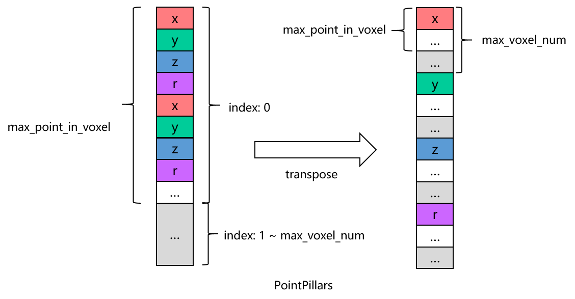
The processing logic of transposition is different, see the figure below for the specific differences.
Note
According to the diagram, CenterPoint and PointPillars have different orders of max_point_in_voxel and max_voxel_num, which leads to different invalid data.
Specifically, the invalid data of PointPillars shows a more concentrated distribution, which is conducive to continuous processing. On the contrary, the invalid data of CenterPoint is scattered among each voxel showing a cross-distribution characteristic. The parameters of the pre-processing will have a certain impact on the implementation efficiency of the operator. We can further consider implementing specific logic according to different parameters.