

Surround View Image Stitching Sample
This sample describes the use of hbVPStitch, hbVPRemap, hbVPJPEGDecode, hbVPJPEGEncode and other APIs, which involves stitches, gdc, and codec hardware ip, to complete a 360-view scene stitching application.
The function realized in this sample is to de-distort and splice the four front-view, right-view, rear-view and left-view distortion maps captured by the fisheye camera on the car, and to complete the application of 360 surround-view scene splicing once. First a map will be created for the four distortion maps, the codec hardware ip will be used to read the fisheye distortion maps and convert them to nv12 data, then the gdc hardware ip will be run to turn the distortion maps into top views, and then the stitch hardware ip will be run to splice the top views into a ring view splice.
The code is mainly divided into the following steps:
- Initialize log and environment variables.
- Set the camera parameters for back, front, left, and right views, and call the ProcessIpmRois() interface to get the top view's roi on the IPM (the coordinate system for image perspective mapping).
- Use the gdc hardware to generate the top view map for the four views, use the codec hardware ip to read the fisheye aberration map to convert it to nv12 data, convert the fisheye aberration data to the top view data, and release the four maps.
- Create the lut table and prepare the information for the splice zone.
- Use the stitch hardware to generate a ring-view stitch map.
- Free the lut table and the requested memory.
Concept Statement
-
VCS (Vehicle Coordinate System) the coordinate system of the vehicle:
The VCS coordinate system describes the coordinate system of the vehicle. The coordinate axes x correspond to the front of the vehicle, y to the left of the vehicle, and z to the top of the vehicle. The origin of this coordinate system is not the center of the vehicle, but the center of the vehicle's rear axle.
-
IPM (Image Perspective Mapping) a coordinate system for image perspective mapping:
The IPM coordinate system describes the coordinate system for image perspective mapping.
Fisheye Aberration Map Conversion Map Generation Details
The main purpose of generating a map is to use the remap function, which can generate pixel mapping relationships:
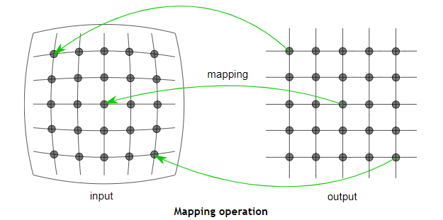
The core function that creates the map that converts the fisheye distortion map to a top view is TransformMapGenerate() , and the main logic is shown in the flowchart:
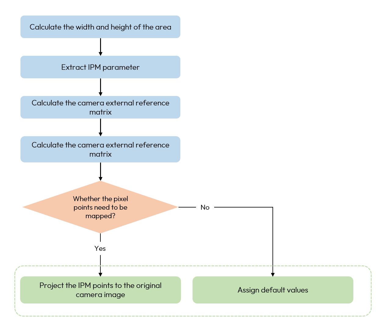
The CalculateExtrinsicTransform() used in TransformMapGenerate() corresponds to the penultimate step in the flowchart,
which converts the vehicle coordinate system data to the camera coordinate system, and the main logic is shown in the flowchart.
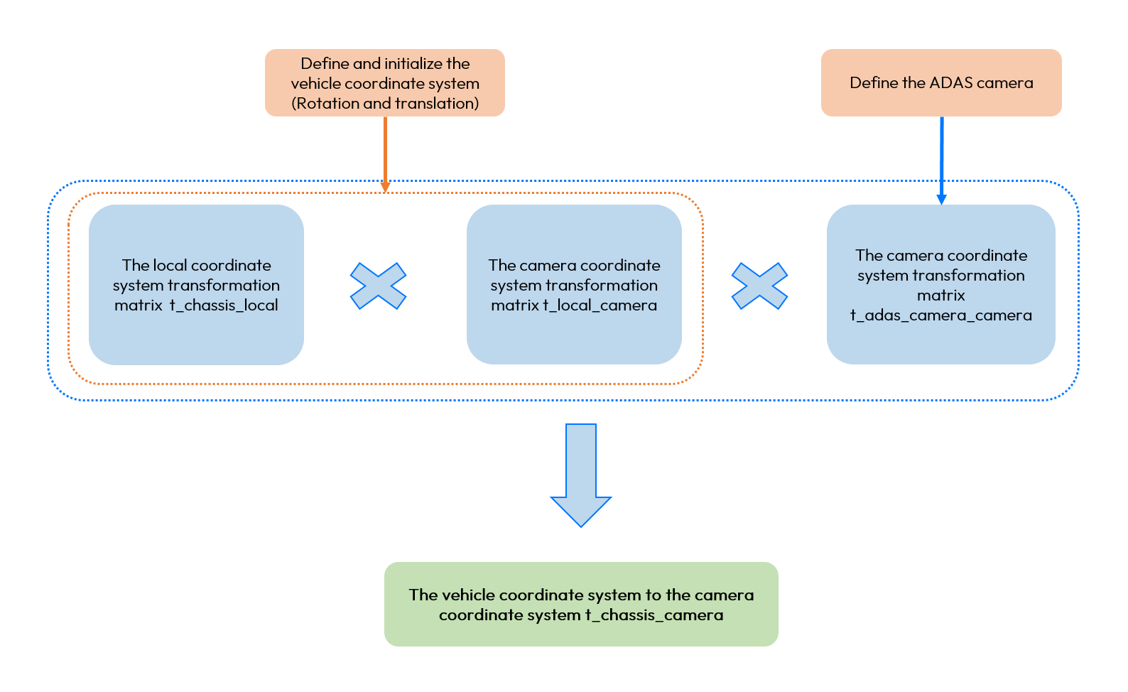
Included among these:
IntrinsicXYZ2R()acts as: converts the euler angle representation of a rotation (Roll-Pitch-Yaw) into a rotation matrix for describing rotational transformations in three-dimensional space. A rotation matrix is able to apply rotation operations to vectors in the form of matrix multiplication.- Adas camera to the camera coordinate system in the transformation matrix.
- The first line indicates the orientation of the new x-Run command line instructions in the imager coordinate system, pointing in the direction of the z-axis in the ADAS imager coordinate system.
- The second line indicates the orientation of the new y-axis in the imager coordinate system, pointing in the direction of the x-axis in the ADAS imager coordinate system.
- The third line indicates the orientation of the new z-axis in the imager coordinate system, pointing in the direction of the y-axis in the ADAS imager coordinate system.
- The last line indicates the panning part, where the last element is 1, indicating no panning.
The function of this matrix is to transform points under the ADAS camera coordinate system to the camera coordinate system, enabling the transformation and alignment of the coordinate system. This transformation is often used in computer graphics and computer vision.
stitch lut table generation details
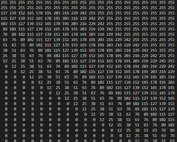
The lut table function serves to indicate the fusion status of each pixel point, with the main purpose of generating transition bands to create a blurring effect.
Explanation: The dump out of the lut table is shown below. 0 and 255 are opposites, 255 is taken as src0 and 0 is taken as src1. 0<x<255, it means take part src0 and get part src1. 128 or 127 is a forced transition band, with numbers on both sides tapering until 0 or tapering to 255, creating a gradient blur effect.
Operating Methods
The sample is located in the vp_samples/script/05_avm directory and contains the following script:
Run command line instructions.
run_avm.sh: this script realizes the sample function of stitching four fisheye aberration maps in a circular view. run_avm.sh script contains the following command line:
${bin}: compiled executable file.
To use it, go to the vp_samples/script/05_avm directory, and execute run_avm.sh as shown in the following code block:
Description of results
The visualization image is generated in the current directory at the end of the sample run. Some of the results are shown as belows:
Original picture:
camera0 (rear view)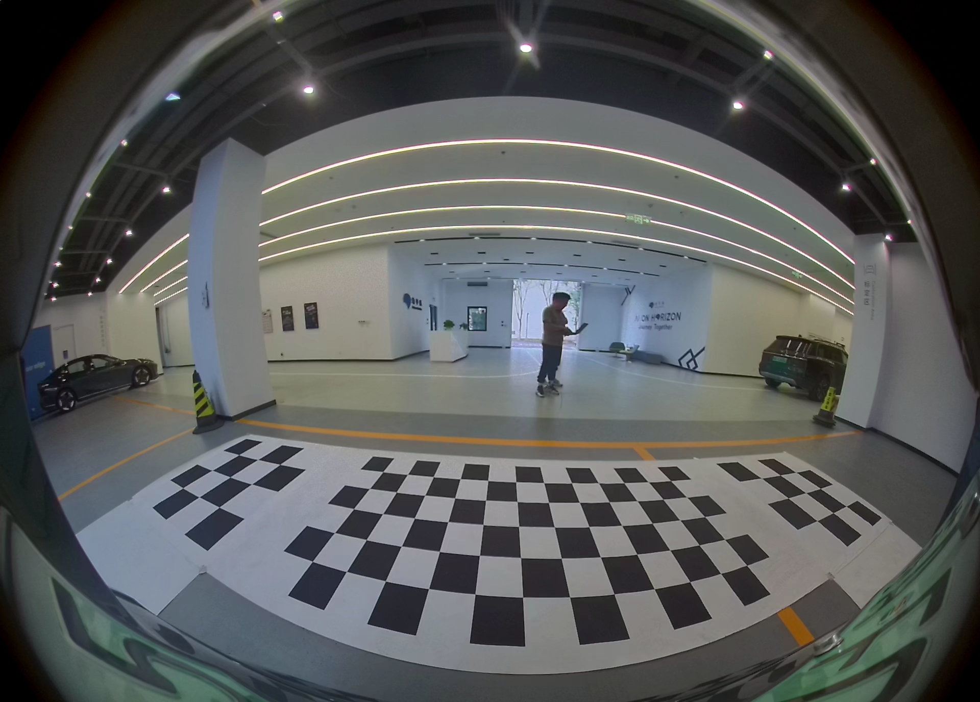 | camera1 (front view)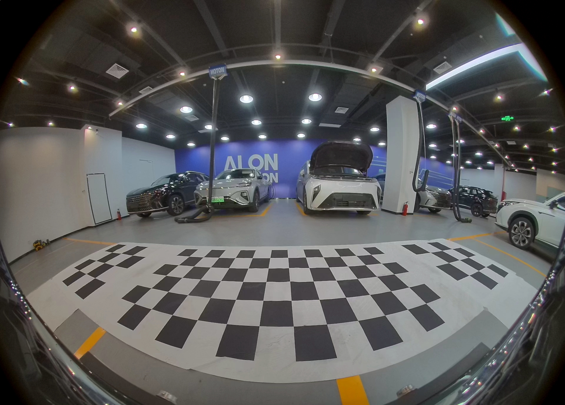 |
camera2 (left view)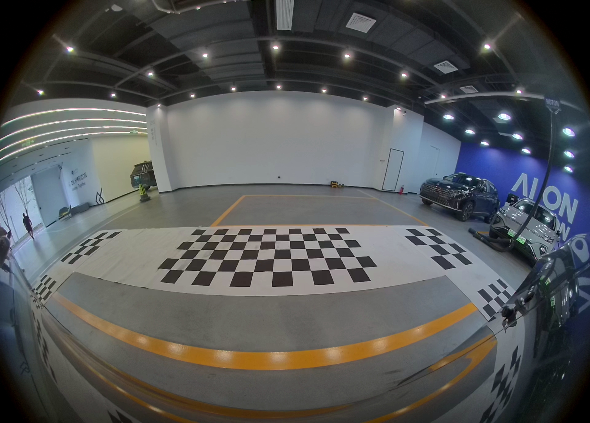 | camera3 (right view)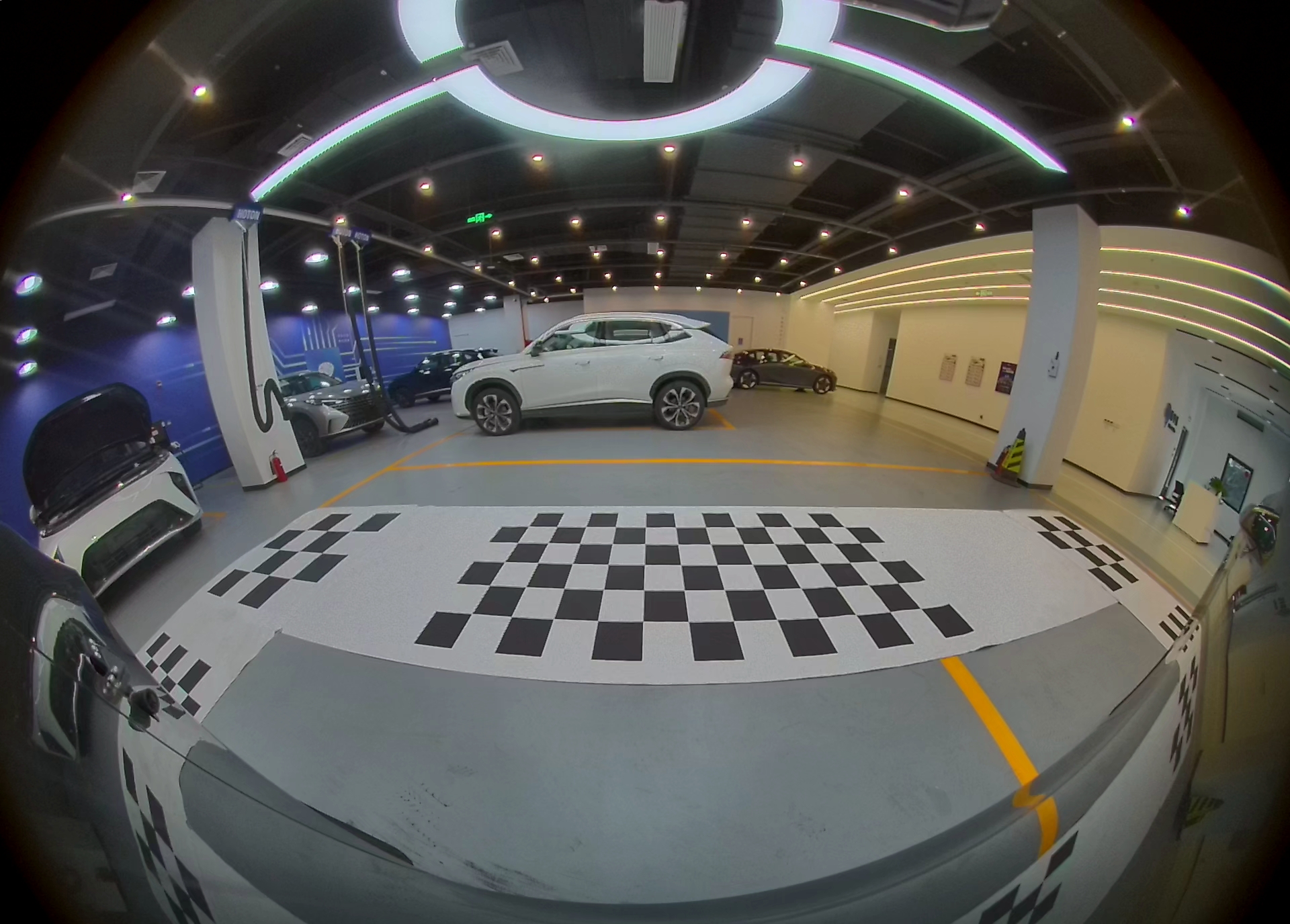 |
De-distortion + top view:
camera0 (rear view)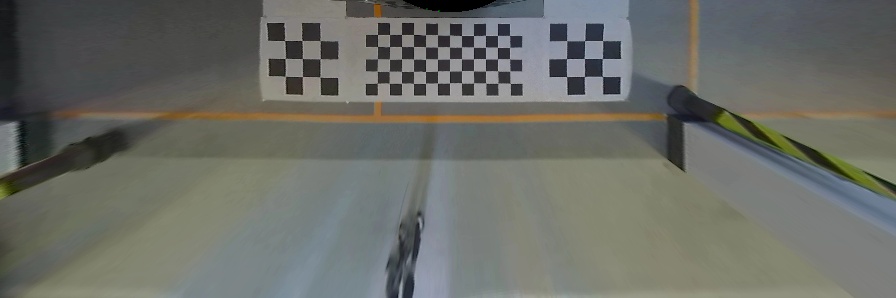 | camera1 (front view)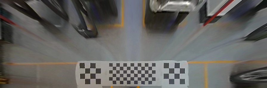 |
camera0 (left view)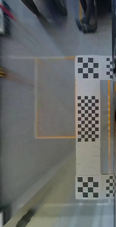 | camera1 (right view)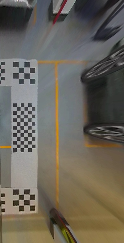 |
Splice around view:
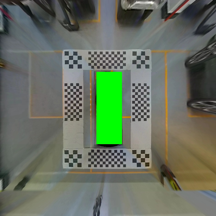
-
The sample remap runs on gdc by default.
-
If you need to replace the picture, please change the camera parameter configuration data corresponding to the picture, otherwise there will be problems with the operation.
-
Environment variables:
HB_AVM_GDC_MAP_DUMPchoose whether dump gdc's map.HB_AVM_GDC_RES_DUMPchoose whether to dump the results of the top view.HB_AVM_LOG_LEVELlog level, 1 for debug. -
When the YUV image is dumped as a JPG file, if the width or height of the YUV image does not satisfy the Codec alignment rules, it will be dumped by default using the opencv method.